Tag Archives: speed reducer gear

China 15KW Cooling Tower Gear Speed Reducer Fan Motor Suppliers gear cycle

Guarantee: 1 yr
Applicable Industries: Constructing Material Shops
Bodyweight (KG): 264 KG
Custom-made assistance: OEM
Gearing Arrangement: Bevel / Miter
Output Torque: 422N.M
Input Velocity: 310R/Min
Output Speed: 325R/Min
Useage: cooling tower
Velocity ratio: 4.43
Fat: 264KG
Sounds: 68
Power: 15kw
Use: cooling tower components
Recent: 31.five
Output velocity: 625
Model: AOSUA
Certification: ISO9001
Packaging Specifics: wood situation packing
Port: HangZhou or ZheJiang

Equipment reducer positive aspects:reduced sound,tiny vibration,effortless routine maintenance.This series have 3 sorts:NGW-F-F31,NGW-L-F61,NGW-F81.The ratio of F13 is 5.sixty seven, Camshaft Pulley Gear For Honda GX35 GX35NT HHT35S UMK435 Engine Motor F81 is5.sixty seven.

Equipment reducer positive aspects:minimal sound,modest vibration,straightforward upkeep.This sequence have 3 varieties:NGW-F-F31,NGW-L-F61,NGW-F81.The ratio of F13 is 5.67, Hailer joyas 2571 assertion dainty necklace 10k 14k 18k gemstone jewellery ladies gold chain necklace F81 is5.sixty seven.

Welcome go to our company’s website,we are professional cooling tower and it’s components manufacturer.We also welcome you to pay a visit to our factory.
Other cooling tower parts : Pump, Supporter , Mid Motor QS 138 70H 3KW Rated electricity V2 mid travel motor with spline shaft Fill

Gear

Spiral Gears for Right-Angle Right-Hand Drives

Spiral gears are used in mechanical systems to transmit torque. The bevel gear is a particular type of spiral gear. It is made up of two gears that mesh with one another. Both gears are connected by a bearing. The two gears must be in mesh alignment so that the negative thrust will push them together. If axial play occurs in the bearing, the mesh will have no backlash. Moreover, the design of the spiral gear is based on geometrical tooth forms.

Equations for spiral gear

The theory of divergence requires that the pitch cone radii of the pinion and gear be skewed in different directions. This is done by increasing the slope of the convex surface of the gear’s tooth and decreasing the slope of the concave surface of the pinion’s tooth. The pinion is a ring-shaped wheel with a central bore and a plurality of transverse axes that are offset from the axis of the spiral teeth.
Spiral bevel gears have a helical tooth flank. The spiral is consistent with the cutter curve. The spiral angle b is equal to the pitch cone’s genatrix element. The mean spiral angle bm is the angle between the genatrix element and the tooth flank. The equations in Table 2 are specific for the Spread Blade and Single Side gears from Gleason.
The tooth flank equation of a logarithmic spiral bevel gear is derived using the formation mechanism of the tooth flanks. The tangential contact force and the normal pressure angle of the logarithmic spiral bevel gear were found to be about twenty degrees and 35 degrees respectively. These two types of motion equations were used to solve the problems that arise in determining the transmission stationary. While the theory of logarithmic spiral bevel gear meshing is still in its infancy, it does provide a good starting point for understanding how it works.
This geometry has many different solutions. However, the main two are defined by the root angle of the gear and pinion and the diameter of the spiral gear. The latter is a difficult one to constrain. A 3D sketch of a bevel gear tooth is used as a reference. The radii of the tooth space profile are defined by end point constraints placed on the bottom corners of the tooth space. Then, the radii of the gear tooth are determined by the angle.
The cone distance Am of a spiral gear is also known as the tooth geometry. The cone distance should correlate with the various sections of the cutter path. The cone distance range Am must be able to correlate with the pressure angle of the flanks. The base radii of a bevel gear need not be defined, but this geometry should be considered if the bevel gear does not have a hypoid offset. When developing the tooth geometry of a spiral bevel gear, the first step is to convert the terminology to pinion instead of gear.
The normal system is more convenient for manufacturing helical gears. In addition, the helical gears must be the same helix angle. The opposite hand helical gears must mesh with each other. Likewise, the profile-shifted screw gears need more complex meshing. This gear pair can be manufactured in a similar way to a spur gear. Further, the calculations for the meshing of helical gears are presented in Table 7-1.
Gear

Design of spiral bevel gears

A proposed design of spiral bevel gears utilizes a function-to-form mapping method to determine the tooth surface geometry. This solid model is then tested with a surface deviation method to determine whether it is accurate. Compared to other right-angle gear types, spiral bevel gears are more efficient and compact. CZPT Gear Company gears comply with AGMA standards. A higher quality spiral bevel gear set achieves 99% efficiency.
A geometric meshing pair based on geometric elements is proposed and analyzed for spiral bevel gears. This approach can provide high contact strength and is insensitive to shaft angle misalignment. Geometric elements of spiral bevel gears are modeled and discussed. Contact patterns are investigated, as well as the effect of misalignment on the load capacity. In addition, a prototype of the design is fabricated and rolling tests are conducted to verify its accuracy.
The three basic elements of a spiral bevel gear are the pinion-gear pair, the input and output shafts, and the auxiliary flank. The input and output shafts are in torsion, the pinion-gear pair is in torsional rigidity, and the system elasticity is small. These factors make spiral bevel gears ideal for meshing impact. To improve meshing impact, a mathematical model is developed using the tool parameters and initial machine settings.
In recent years, several advances in manufacturing technology have been made to produce high-performance spiral bevel gears. Researchers such as Ding et al. optimized the machine settings and cutter blade profiles to eliminate tooth edge contact, and the result was an accurate and large spiral bevel gear. In fact, this process is still used today for the manufacturing of spiral bevel gears. If you are interested in this technology, you should read on!
The design of spiral bevel gears is complex and intricate, requiring the skills of expert machinists. Spiral bevel gears are the state of the art for transferring power from one system to another. Although spiral bevel gears were once difficult to manufacture, they are now common and widely used in many applications. In fact, spiral bevel gears are the gold standard for right-angle power transfer.While conventional bevel gear machinery can be used to manufacture spiral bevel gears, it is very complex to produce double bevel gears. The double spiral bevel gearset is not machinable with traditional bevel gear machinery. Consequently, novel manufacturing methods have been developed. An additive manufacturing method was used to create a prototype for a double spiral bevel gearset, and the manufacture of a multi-axis CNC machine center will follow.
Spiral bevel gears are critical components of helicopters and aerospace power plants. Their durability, endurance, and meshing performance are crucial for safety. Many researchers have turned to spiral bevel gears to address these issues. One challenge is to reduce noise, improve the transmission efficiency, and increase their endurance. For this reason, spiral bevel gears can be smaller in diameter than straight bevel gears. If you are interested in spiral bevel gears, check out this article.
Gear

Limitations to geometrically obtained tooth forms

The geometrically obtained tooth forms of a spiral gear can be calculated from a nonlinear programming problem. The tooth approach Z is the linear displacement error along the contact normal. It can be calculated using the formula given in Eq. (23) with a few additional parameters. However, the result is not accurate for small loads because the signal-to-noise ratio of the strain signal is small.
Geometrically obtained tooth forms can lead to line and point contact tooth forms. However, they have their limits when the tooth bodies invade the geometrically obtained tooth form. This is called interference of tooth profiles. While this limit can be overcome by several other methods, the geometrically obtained tooth forms are limited by the mesh and strength of the teeth. They can only be used when the meshing of the gear is adequate and the relative motion is sufficient.
During the tooth profile measurement, the relative position between the gear and the LTS will constantly change. The sensor mounting surface should be parallel to the rotational axis. The actual orientation of the sensor may differ from this ideal. This may be due to geometrical tolerances of the gear shaft support and the platform. However, this effect is minimal and is not a serious problem. So, it is possible to obtain the geometrically obtained tooth forms of spiral gear without undergoing expensive experimental procedures.
The measurement process of geometrically obtained tooth forms of a spiral gear is based on an ideal involute profile generated from the optical measurements of one end of the gear. This profile is assumed to be almost perfect based on the general orientation of the LTS and the rotation axis. There are small deviations in the pitch and yaw angles. Lower and upper bounds are determined as – 10 and -10 degrees respectively.
The tooth forms of a spiral gear are derived from replacement spur toothing. However, the tooth shape of a spiral gear is still subject to various limitations. In addition to the tooth shape, the pitch diameter also affects the angular backlash. The values of these two parameters vary for each gear in a mesh. They are related by the transmission ratio. Once this is understood, it is possible to create a gear with a corresponding tooth shape.
As the length and transverse base pitch of a spiral gear are the same, the helix angle of each profile is equal. This is crucial for engagement. An imperfect base pitch results in an uneven load sharing between the gear teeth, which leads to higher than nominal loads in some teeth. This leads to amplitude modulated vibrations and noise. In addition, the boundary point of the root fillet and involute could be reduced or eliminate contact before the tip diameter.

China 15KW Cooling Tower Gear Speed Reducer Fan Motor Suppliers     gear cycleChina 15KW Cooling Tower Gear Speed Reducer Fan Motor Suppliers     gear cycle
editor by Cx 2023-06-27

China 2.5 SWL worm gear screw jack screw lifter 25kN speed reducer cycle gear

Guarantee: 1 12 months
Applicable Industries: Producing Plant, Food & Beverage Manufacturing facility, Design works , Strength & Mining
Bodyweight (KG): ten KG
Tailored assist: OEM, ODM, OBM
Gearing Arrangement: Worm
Output Torque: 2.9-2040N.m, 2.9-2040N.m
Enter Speed: 750-fifteen For BMW stone, woodworking, chemical, lifting, mining, petroleum, textile, health care, maritime ships and other industries, and are broadly praised by domestic and international buyers. “Steady refinement, seeking a CZPT predicament” is our CZPT goal. We constantly purpose to offer our buyers with trustworthy and sturdy reducers. We welcome new and previous customers from all the globe to speak to us for foreseeable future company interactions and reaching mutual success! Why Choose Us 1. 6 kinds of innovative manufacturing & take a look at products to guarantee accuracy & stable operationtwo. fifty+ expert staff with responsibilitythree. Stringent QC staff4. Offer trustworthy & durable products with aggressive pricesfive. Responsive & Skilled income groupsix. Experts with thirty+ years industrial and item expertise7. Quick supply time Generation and screening equipment CNC Worm Gear Bogging Equipment CNC Worm Grinding Machine CNC Lathe Warehouse Well-placed Spare Parts Housing Processing Assembly Workshop Air Tightness Examination Equipment And Shaft Measuring Device Packing & Supply FAQ Q1: What information ought to I tell you to get a quote?A1: Remember to recommend us sort of pace reducer, model/size, ratio, energy, purchase amount or other specifications, we will send out you comprehensive quotation. If you are not distinct about which reducer you need, remember to explain to us your prerequisite as a lot as attainable, we will aid you pick types. Q2: How is your good quality?A2: As a skilled gearbox supplier above 10 several years, 3ton Weighty Lifting VT Lever Chain Hoist Pulley Block with Safety Hook we usually consider products quality as the best precedence of company growth. We by no means cut corners on merchandise substance and processing. Each of our resources and reducers are rigorously inspected by specialist high quality control personnel, ensuring that the items provided to buyers are trustworthy and resilient.Q3: What is your minimal purchase amount?A3: Our MOQ is from 1pc, any customer’s requirements or orders will be valued, and we are willing to give our customers with greatest support.Q4: Can you make OEM/ODM orders?A4: Of course, we have rich expertise on OEM/ODM orders. You should check with our income group for more particulars.Q5: Do you offer samples?A5: Of course, samples are offered for quality analysis, and sample cost will be refunded from formal order.Q6: What sort of packaging do you use?A6: Normally we use packaging 5 layer of export normal cartons, plywood pallets, plywood instances. The packing depends on dimension and excess weight of different gearboxes, we will make confident every single gearbox will be safeguarded properly to keep away from harm throughout transportation.Q7: What is your supply conditions and payment terms?A7: EXW, FOB(HangZhou/ZheJiang ), CFR, CIF, DAP,DDP are offered.We accept T/T(thirty% payment as deposit, 70% payment just before shipment), L/C, Cash. Associated pictures or movies of concluded goods will be provided prior to your harmony payment. And inspection from your aspect is also approved.Q8: How prolonged is your guide time? How do you assure on-time supply?A8: For FCL get, 30-forty days right after obtaining your deposit, urgent get can be concluded in fifteen-20days. For LCL purchase, it will get 7-15days.Q9: How to deliver the items?A9: by sea – consumer appoints the forwarder, or our income crew finds suited forwarder for consumers.by air – consumer supply acquire categorical account, or our revenue crew finds ideal convey for consumers, Rapid transmission gearbox elements synchronizer A-C09005 for ZheJiang Vehicle Xihu (West Lake) Dis.feng CZPT truck spare components mostly for sample or urgent order.Our organization can also arrange to supply the items to some places in China appointed by buyers.Q10: How long is your merchandise warranty period?A10: Our guarantee interval is 1 year given that cargo day.

Gear

Hypoid Bevel Vs Straight Spiral Bevel – What’s the Difference?

Spiral gears come in many different varieties, but there is a fundamental difference between a Hypoid bevel gear and a Straight spiral bevel. This article will describe the differences between the two types of gears and discuss their use. Whether the gears are used in industrial applications or at home, it is vital to understand what each type does and why it is important. Ultimately, your final product will depend on these differences.

Hypoid bevel gears

In automotive use, hypoid bevel gears are used in the differential, which allows the wheels to rotate at different speeds while maintaining the vehicle’s handling. This gearbox assembly consists of a ring gear and pinion mounted on a carrier with other bevel gears. These gears are also widely used in heavy equipment, auxiliary units, and the aviation industry. Listed below are some common applications of hypoid bevel gears.
For automotive applications, hypoid gears are commonly used in rear axles, especially on large trucks. Their distinctive shape allows the driveshaft to be located deeper in the vehicle, thus lowering the center of gravity and minimizing interior disruption. This design makes the hypoid gearset one of the most efficient types of gearboxes on the market. In addition to their superior efficiency, hypoid gears are very easy to maintain, as their mesh is based on sliding action.
The face-hobbed hypoid gears have a characteristic epicycloidal lead curve along their lengthwise axis. The most common grinding method for hypoid gears is the Semi-Completing process, which uses a cup-shaped grinding wheel to replace the lead curve with a circular arc. However, this method has a significant drawback – it produces non-uniform stock removal. Furthermore, the grinding wheel cannot finish all the surface of the tooth.
The advantages of a hypoid gear over a spiral bevel gear include a higher contact ratio and a higher transmission torque. These gears are primarily used in automobile drive systems, where the ratio of a single pair of hypoid gears is the highest. The hypoid gear can be heat-treated to increase durability and reduce friction, making it an ideal choice for applications where speed and efficiency are critical.
The same technique used in spiral bevel gears can also be used for hypoid bevel gears. This machining technique involves two-cut roughing followed by one-cut finishing. The pitch diameter of hypoid gears is up to 2500 mm. It is possible to combine the roughing and finishing operations using the same cutter, but the two-cut machining process is recommended for hypoid gears.
The advantages of hypoid gearing over spiral bevel gears are primarily based on precision. Using a hypoid gear with only three arc minutes of backlash is more efficient than a spiral bevel gear that requires six arc minutes of backlash. This makes hypoid gears a more viable choice in the motion control market. However, some people may argue that hypoid gears are not practical for automobile assemblies.
Hypoid gears have a unique shape – a cone that has teeth that are not parallel. Their pitch surface consists of two surfaces – a conical surface and a line-contacting surface of revolution. An inscribed cone is a common substitute for the line-contact surface of hypoid bevel gears, and it features point-contacts instead of lines. Developed in the early 1920s, hypoid bevel gears are still used in heavy truck drive trains. As they grow in popularity, they are also seeing increasing use in the industrial power transmission and motion control industries.
Gear

Straight spiral bevel gears

There are many differences between spiral bevel gears and the traditional, non-spiral types. Spiral bevel gears are always crowned and never conjugated, which limits the distribution of contact stress. The helical shape of the bevel gear is also a factor of design, as is its length. The helical shape has a large number of advantages, however. Listed below are a few of them.
Spiral bevel gears are generally available in pitches ranging from 1.5 to 2500 mm. They are highly efficient and are also available in a wide range of tooth and module combinations. Spiral bevel gears are extremely accurate and durable, and have low helix angles. These properties make them excellent for precision applications. However, some gears are not suitable for all applications. Therefore, you should consider the type of bevel gear you need before purchasing.
Compared to helical gears, straight bevel gears are easier to manufacture. The earliest method used to manufacture these gears was the use of a planer with an indexing head. However, with the development of modern manufacturing processes such as the Revacycle and Coniflex systems, manufacturers have been able to produce these gears more efficiently. Some of these gears are used in windup alarm clocks, washing machines, and screwdrivers. However, they are particularly noisy and are not suitable for automobile use.
A straight bevel gear is the most common type of bevel gear, while a spiral bevel gear has concave teeth. This curved design produces a greater amount of torque and axial thrust than a straight bevel gear. Straight teeth can increase the risk of breaking and overheating equipment and are more prone to breakage. Spiral bevel gears are also more durable and last longer than helical gears.
Spiral and hypoid bevel gears are used for applications with high peripheral speeds and require very low friction. They are recommended for applications where noise levels are essential. Hypoid gears are suitable for applications where they can transmit high torque, although the helical-spiral design is less effective for braking. For this reason, spiral bevel gears and hypoids are generally more expensive. If you are planning to buy a new gear, it is important to know which one will be suitable for the application.
Spiral bevel gears are more expensive than standard bevel gears, and their design is more complex than that of the spiral bevel gear. However, they have the advantage of being simpler to manufacture and are less likely to produce excessive noise and vibration. They also have less teeth to grind, which means that they are not as noisy as the spiral bevel gears. The main benefit of this design is their simplicity, as they can be produced in pairs, which saves money and time.
In most applications, spiral bevel gears have advantages over their straight counterparts. They provide more evenly distributed tooth loads and carry more load without surface fatigue. The spiral angle of the teeth also affects thrust loading. It is possible to make a straight spiral bevel gear with two helical axes, but the difference is the amount of thrust that is applied to each individual tooth. In addition to being stronger, the spiral angle provides the same efficiency as the straight spiral gear.
Gear

Hypoid gears

The primary application of hypoid gearboxes is in the automotive industry. They are typically found on the rear axles of passenger cars. The name is derived from the left-hand spiral angle of the pinion and the right-hand spiral angle of the crown. Hypoid gears also benefit from an offset center of gravity, which reduces the interior space of cars. Hypoid gears are also used in heavy trucks and buses, where they can improve fuel efficiency.
The hypoid and spiral bevel gears can be produced by face-hobbing, a process that produces highly accurate and smooth-surfaced parts. This process enables precise flank surfaces and pre-designed ease-off topographies. These processes also enhance the mechanical resistance of the gears by 15 to 20%. Additionally, they can reduce noise and improve mechanical efficiency. In commercial applications, hypoid gears are ideal for ensuring quiet operation.
Conjugated design enables the production of hypoid gearsets with length or profile crowning. Its characteristic makes the gearset insensitive to inaccuracies in the gear housing and load deflections. In addition, crowning allows the manufacturer to adjust the operating displacements to achieve the desired results. These advantages make hypoid gear sets a desirable option for many industries. So, what are the advantages of hypoid gears in spiral gears?
The design of a hypoid gear is similar to that of a conventional bevel gear. Its pitch surfaces are hyperbolic, rather than conical, and the teeth are helical. This configuration also allows the pinion to be larger than an equivalent bevel pinion. The overall design of the hypoid gear allows for large diameter shafts and a large pinion. It can be considered a cross between a bevel gear and a worm drive.
In passenger vehicles, hypoid gears are almost universal. Their smoother operation, increased pinion strength, and reduced weight make them a desirable choice for many vehicle applications. And, a lower vehicle body also lowers the vehicle’s body. These advantages made all major car manufacturers convert to hypoid drive axles. It is worth noting that they are less efficient than their bevel gear counterparts.
The most basic design characteristic of a hypoid gear is that it carries out line contact in the entire area of engagement. In other words, if a pinion and a ring gear rotate with an angular increment, line contact is maintained throughout their entire engagement area. The resulting transmission ratio is equal to the angular increments of the pinion and ring gear. Therefore, hypoid gears are also known as helical gears.

China 2.5 SWL worm gear screw jack screw lifter 25kN speed reducer     cycle gearChina 2.5 SWL worm gear screw jack screw lifter 25kN speed reducer     cycle gear
editor by Cx 2023-06-15

China big torque right angle motor gearbox 90 degree right angle 90 degree servo motor gearbox speed reducer gear box for algriculture worm gearbox

Guarantee: 3 several years
Relevant Industries: Lodges, Garment Shops, Constructing Materials Stores, Production Plant, Machinery Mend Retailers, Meals & Beverage Manufacturing facility, Farms, Cafe, Retail, Foodstuff Store, Printing Retailers, Design works , Energy & Mining, Foods & Beverage Outlets, Advertising Organization
Bodyweight (KG): fifty six KG
Personalized help: OEM, ODM, OBM
Gearing Arrangement: Bevel / Miter
Output Torque: Up to 3378Nm
Enter Pace: 750-1500rpm
Output Velocity: 3~1450r/min
Certification: ISO9001-2008
Mount Placement: Foot Mounted
Bearing: C&U
gear precision quality: din 4
Packaging Particulars: Common wooden case

Goods Description SLT -Much more link sort and many others.Screw jak is utilized to all fields for lifting or pulling, CZPT 705C 706C Planetary Gearbox for cold milling device W2100 W1900 this kind of as Aircraft servicing platform, Solar plate, equipment, metallurgy, water conservancy, health-related treatment method, chemical industry, culture and hygienist and so forth.Specs:1.Tseries sprial bevel gear reducer with various types are standardized2.all ratio of 1:1,1.5:12:twelve.5:13:fourteen:1and 5:1 are real kinds,3.regular effectiveness is ninety eight%. Benefit: -Self-locking ability -Can be driven directly by motor or other power -Can be custom-made according user’sdemand -Compact configuration, little dimensions, Japanese tractors PTO inversor transmission gearbox light-weight -Convenient set up, adaptable procedure -Higher reliability andstability -Prolonged provider daily life Correct elevation Remaining elevation Front elevation

Product IdentifyT sequence Spiral Bevel Gearbox
model no.T2, T4, T6, T7, T8, T10, T12, T16, T20, T25
Ratio1:1, 1.5:1, 2:1, 2.5:1,3:1,4:1,5:one
gear Materialhigh quality artificial CZPT 50CrMnT
Gear ProcessingGrinding finish by HOFLER Grinding Equipment, WGB-NYH Worm Planetary Gear Speed Reducer Motor Wheel Gearbox 28~86 Rpm .fifty six~1.65 Rpm for Irrigation Program 70000 Lb.in Mcmaster Precision quality : DIN four
spindlehigh purity steel alloy 40Cr piece
Noise CheckBellow 65dB
Warranty1 12 months
8Max. torque
Business Profile certificates Packing & Shipping and delivery Packing Particulars: Standard carton/Pallet/Normal picket caseDelivery Details : 15-30 working days CZPT payment FAQ 1.Payment Term: TT, L/C2.Supply time: about 30 times from acquire payment. 3.We accept customized items as for every your special requirement.4.Xihu (West Lake) Dis.strains for the Choice:Usually we can decide on 1 machine which is ideal for you with some informations from you,this sort of asratio/motor velocity/mounting dimension/ out torque etc. 5.If the minimum buy sum is in excessive of $10000, there are preferential.Q1: What details ought to I notify you to affirm the solution?A:Model/Dimensions, Transmission Ratio, Shaft directions & Order quantity.Q2: What can i do if I never know which 1 I need?A:Dont worry, Send out as considerably information as you can, our staff will aid you find the appropriate 1 you are searching for.Q3: What is your item warranty period?A:We supply 1 yr guarantee since the vessel departure day left China.Q4: Are you investing firm or producer ?A: We are factory.Q5: How lengthy is your supply time?A: Normally it is 5-10 days if the items are in stock. or it is 15-20 days if the goods are not in inventory, it is in accordance toquantity.Q6: Do you provide samples ? is it totally free or additional ?A: Of course, we could offer the sample for free of charge cost but do not shell out the cost of freight.Q7: What is your terms of payment ?A: Payment=1000USD, 30% T/T in advance , Model new 4JB1 gearbox for 4JB1 engine equilibrium just before shippment.If you have any other inquiries, remember to really feel cost-free to contact us as demonstrated under, you can simply click on the graphic underneath to get in touch with medirectly. Related Merchandise You can click on on the photo to look through other products. Contact Us

Gear

How to Compare Different Types of Spur Gears

When comparing different types of spur gears, there are several important considerations to take into account. The main considerations include the following: Common applications, Pitch diameter, and Addendum circle. Here we will look at each of these factors in more detail. This article will help you understand what each type of spur gear can do for you. Whether you’re looking to power an electric motor or a construction machine, the right gear for the job will make the job easier and save you money in the long run.

Common applications

Among its many applications, a spur gear is widely used in airplanes, trains, and bicycles. It is also used in ball mills and crushers. Its high speed-low torque capabilities make it ideal for a variety of applications, including industrial machines. The following are some of the common uses for spur gears. Listed below are some of the most common types. While spur gears are generally quiet, they do have their limitations.
A spur gear transmission can be external or auxiliary. These units are supported by front and rear casings. They transmit drive to the accessory units, which in turn move the machine. The drive speed is typically between 5000 and 6000 rpm or 20,000 rpm for centrifugal breathers. For this reason, spur gears are typically used in large machinery. To learn more about spur gears, watch the following video.
The pitch diameter and diametral pitch of spur gears are important parameters. A diametral pitch, or ratio of teeth to pitch diameter, is important in determining the center distance between two spur gears. The center distance between two spur gears is calculated by adding the radius of each pitch circle. The addendum, or tooth profile, is the height by which a tooth projects above the pitch circle. Besides pitch, the center distance between two spur gears is measured in terms of the distance between their centers.
Another important feature of a spur gear is its low speed capability. It can produce great power even at low speeds. However, if noise control is not a priority, a helical gear is preferable. Helical gears, on the other hand, have teeth arranged in the opposite direction of the axis, making them quieter. However, when considering the noise level, a helical gear will work better in low-speed situations.

Construction

The construction of spur gear begins with the cutting of the gear blank. The gear blank is made of a pie-shaped billet and can vary in size, shape, and weight. The cutting process requires the use of dies to create the correct gear geometry. The gear blank is then fed slowly into the screw machine until it has the desired shape and size. A steel gear blank, called a spur gear billet, is used in the manufacturing process.
A spur gear consists of two parts: a centre bore and a pilot hole. The addendum is the circle that runs along the outermost points of a spur gear’s teeth. The root diameter is the diameter at the base of the tooth space. The plane tangent to the pitch surface is called the pressure angle. The total diameter of a spur gear is equal to the addendum plus the dedendum.
The pitch circle is a circle formed by a series of teeth and a diametrical division of each tooth. The pitch circle defines the distance between two meshed gears. The center distance is the distance between the gears. The pitch circle diameter is a crucial factor in determining center distances between two mating spur gears. The center distance is calculated by adding the radius of each gear’s pitch circle. The dedendum is the height of a tooth above the pitch circle.
Other considerations in the design process include the material used for construction, surface treatments, and number of teeth. In some cases, a standard off-the-shelf gear is the most appropriate choice. It will meet your application needs and be a cheaper alternative. The gear will not last for long if it is not lubricated properly. There are a number of different ways to lubricate a spur gear, including hydrodynamic journal bearings and self-contained gears.
Gear

Addendum circle

The pitch diameter and addendum circle are two important dimensions of a spur gear. These diameters are the overall diameter of the gear and the pitch circle is the circle centered around the root of the gear’s tooth spaces. The addendum factor is a function of the pitch circle and the addendum value, which is the radial distance between the top of the gear tooth and the pitch circle of the mating gear.
The pitch surface is the right-hand side of the pitch circle, while the root circle defines the space between the two gear tooth sides. The dedendum is the distance between the top of the gear tooth and the pitch circle, and the pitch diameter and addendum circle are the two radial distances between these two circles. The difference between the pitch surface and the addendum circle is known as the clearance.
The number of teeth in the spur gear must not be less than 16 when the pressure angle is twenty degrees. However, a gear with 16 teeth can still be used if its strength and contact ratio are within design limits. In addition, undercutting can be prevented by profile shifting and addendum modification. However, it is also possible to reduce the addendum length through the use of a positive correction. However, it is important to note that undercutting can happen in spur gears with a negative addendum circle.
Another important aspect of a spur gear is its meshing. Because of this, a standard spur gear will have a meshing reference circle called a Pitch Circle. The center distance, on the other hand, is the distance between the center shafts of the two gears. It is important to understand the basic terminology involved with the gear system before beginning a calculation. Despite this, it is essential to remember that it is possible to make a spur gear mesh using the same reference circle.

Pitch diameter

To determine the pitch diameter of a spur gear, the type of drive, the type of driver, and the type of driven machine should be specified. The proposed diametral pitch value is also defined. The smaller the pitch diameter, the less contact stress on the pinion and the longer the service life. Spur gears are made using simpler processes than other types of gears. The pitch diameter of a spur gear is important because it determines its pressure angle, the working depth, and the whole depth.
The ratio of the pitch diameter and the number of teeth is called the DIAMETRAL PITCH. The teeth are measured in the axial plane. The FILLET RADIUS is the curve that forms at the base of the gear tooth. The FULL DEPTH TEETH are the ones with the working depth equal to 2.000 divided by the normal diametral pitch. The hub diameter is the outside diameter of the hub. The hub projection is the distance the hub extends beyond the gear face.
A metric spur gear is typically specified with a Diametral Pitch. This is the number of teeth per inch of the pitch circle diameter. It is generally measured in inverse inches. The normal plane intersects the tooth surface at the point where the pitch is specified. In a helical gear, this line is perpendicular to the pitch cylinder. In addition, the pitch cylinder is normally normal to the helix on the outside.
The pitch diameter of a spur gear is typically specified in millimeters or inches. A keyway is a machined groove on the shaft that fits the key into the shaft’s keyway. In the normal plane, the pitch is specified in inches. Involute pitch, or diametral pitch, is the ratio of teeth per inch of diameter. While this may seem complicated, it’s an important measurement to understand the pitch of a spur gear.
gear

Material

The main advantage of a spur gear is its ability to reduce the bending stress at the tooth no matter the load. A typical spur gear has a face width of 20 mm and will fail when subjected to 3000 N. This is far more than the yield strength of the material. Here is a look at the material properties of a spur gear. Its strength depends on its material properties. To find out what spur gear material best suits your machine, follow the following steps.
The most common material used for spur gears is steel. There are different kinds of steel, including ductile iron and stainless steel. S45C steel is the most common steel and has a 0.45% carbon content. This type of steel is easily obtainable and is used for the production of helical, spur, and worm gears. Its corrosion resistance makes it a popular material for spur gears. Here are some advantages and disadvantages of steel.
A spur gear is made of metal, plastic, or a combination of these materials. The main advantage of metal spur gears is their strength to weight ratio. It is about one third lighter than steel and resists corrosion. While aluminum is more expensive than steel and stainless steel, it is also easier to machine. Its design makes it easy to customize for the application. Its versatility allows it to be used in virtually every application. So, if you have a specific need, you can easily find a spur gear that fits your needs.
The design of a spur gear greatly influences its performance. Therefore, it is vital to choose the right material and measure the exact dimensions. Apart from being important for performance, dimensional measurements are also important for quality and reliability. Hence, it is essential for professionals in the industry to be familiar with the terms used to describe the materials and parts of a gear. In addition to these, it is essential to have a good understanding of the material and the dimensional measurements of a gear to ensure that production and purchase orders are accurate.

China big torque right angle motor gearbox 90 degree right angle 90 degree servo motor gearbox speed reducer gear box for algriculture     worm gearboxChina big torque right angle motor gearbox 90 degree right angle 90 degree servo motor gearbox speed reducer gear box for algriculture     worm gearbox
editor by czh 2023-04-19

China Jwb-X Stepless Speed Variator Geared Reducer for Drying Machine gear patrol

Solution Description

JWB Sequence Pace Variator 
1. Attributes:

 JWB-X  type

  • Measurements: ≥04
  • Power up to 1.5 kW or more
  • Circumstances in RAL 5571 blue cast iron
  • Shafts: scenario hardened and tempered steel.
  • Internal parts: heat-taken care of metal
  • Output pace with 4 pole(1400r/min) motors: 2-10r/min4.7-23.5r/min15-75r/min20-100r/min, 28-140r/min, 30-150r/min40-200r/min60-300r/min80-400r/min100-500r/min190-950r/min.
  • Output Torque worth max 1002Nm
  • Silent, vibration-free operating
  • Bidirectional rotation
  • Handle handwheel positionable on both facet
  • Slipping velocity to max load at 5% 
  • Regulation sensibility: ,5 rpm 
  • Painted with blue epoxy-polyester powder 

 JWB-X B type

  • Sizes:01,02,03 and 04
  • Electrical power up to 1.5 kW or less
  • Circumstances in die-forged aluminium alloy
  • Shafts: scenario hardened and tempered metal.
  • Interior factors: heat-dealt with metal
  • Output pace with 4 pole(1400r/min) motors: 2r/min-20r/min4.7r/min-23.5r/min6.5-32.5r/min, 8-40r/min, 9-45r/min, thirteen-65r/min, 15r/min-75r/min18-90r/min, 25-125r/min, 28r/min-140r/min40r/min-200r/min60r/min-300r/min80r/min-400r/min100r/min-500r/min190r/min-950r/min.
  • Output Torque worth max 795 Nm
  • Silent, vibration-cost-free working
  • Bidirectional rotation
  • Control hand wheel positionable on either aspect
  • Slipping velocity to max load at 5%
  • Regulation sensibility: ,5 rpm
  • Painted with blue epoxy-polyester powder 

two. Specialized parameters


Type Output Torque Output Shaft Dia.   Output Speed Variety 2rpm-950rpm
SWB01 two.6-1.6N.m φ11 Applicable Motor Power .18kW-7.5kW
SWB02 258-1.8N.m φ14,φ24,φ28,φ32  
SWB03 426-4N.m φ24,φ28,φ38 Input Choices With Inline AC Motor
SWB04 795-8N.m φ28,φ38,φ42 With IEC Motor
SWB05 535-16N.m φ38,φ48,φ55 With Input Shaft
SWB06 1002-40N.m φ42,φ55,φ70 With Enter Flange

About Us

ZheJiang CZPT Drive Co.,Ltd,the predecessor was a point out-owned navy mould business, was proven in 1965. CZPT specializes in the comprehensive energy transmission resolution for high-conclude gear production industries based mostly on the goal of “System Merchandise, Software Design and style and Expert Service”.
Starshine have a sturdy specialized power with above 350 staff at existing, like over thirty engineering professionals, 30 quality inspectors, masking an spot of 80000 sq. CZPT and sorts of sophisticated processing machines and screening equipments. We have a good foundation for the market application advancement and services of higher-conclude pace reducers & variators proudly owning to the provincial engineering technologies study heart,the lab of gear pace reducers, and the foundation of modern R&D.

Our Group

Good quality Manage
Quality:Insist on Improvement,Strive for Excellence With the development of equipment manufacturing indurstry,customer never satirsfy with the current quality of our products,on the contrary,wcreate the value of quality.
Quality policy:to enhance the overall level in the field of power transmission  
Quality View:Continuous Improvement , pursuit of excellence
Quality Philosophy:Quality creates value

three. Incoming Quality Control
To establish the AQL acceptable level of incoming material control, to provide the material for the whole inspection, sampling, immunity. On the acceptance of qualified products to warehousing, substandard goods to take return, check, rework, rework inspection responsible for tracking bad, to monitor the supplier to take corrective 
measures to prevent recurrence.

four. Process Quality Control
The manufacturing site of the first examination, inspection and final inspection, sampling according to the requirements of some projects, judging the quality change trend
 found abnormal phenomenon of manufacturing, and supervise the production department to improve, eliminate the abnormal phenomenon or state.

5. FQC(Final QC)
After the manufacturing department will complete the product, stand in the customer’s position on the finished product quality verification, in order to ensure the quality of 
customer expectations and needs.

six. OQC(Outgoing QC)
After the product sample inspection to determine the qualified, allowing storage, but when the finished product from the warehouse before the formal delivery of the goods, there is a check, this is called the shipment inspection.Check content:In the warehouse storage and transfer status to confirm, while confirming the delivery of the 
product is a product inspection to determine the qualified products.

7. Certification.

Packing

Shipping

Type: Glass Washing and Drying Machine
Certification: CE, ISO, CQC,SGS,TUV
Structure: Horizontal
Control System: Manual Adjustment
Glass Washing Machine Type: Transmission Parts
Glass Edging Machine Type: Glass Round Edging Machine

###

Samples:
US$ 300/Piece
1 Piece(Min.Order)

|
Request Sample

###

Customization:
Available

|


###

Type Output Torque Output Shaft Dia.   Output Speed Range 2rpm-950rpm
SWB01 2.6-1.6N.m φ11 Applicable Motor Power 0.18kW-7.5kW
SWB02 258-1.8N.m φ14,φ24,φ28,φ32  
SWB03 426-4N.m φ24,φ28,φ38 Input Options With Inline AC Motor
SWB04 795-8N.m φ28,φ38,φ42 With IEC Motor
SWB05 535-16N.m φ38,φ48,φ55 With Input Shaft
SWB06 1002-40N.m φ42,φ55,φ70 With Input Flange

Types of Bevel Gears

Bevel Gears are used in a number of industries. They are used in wheeled excavators, dredges, conveyor belts, mill actuators, and rail transmissions. A bevel gear’s spiral or angled bevel can make it suitable for confined spaces. It is also used in robotics and vertical supports of rolling mills. You can use bevel gears in food processing processes. For more information on bevel gears, read on.
gear

Spiral bevel gear

Spiral bevel gears are used to transmit power between two shafts in a 90-degree orientation. They have curved or oblique teeth and can be fabricated from various metals. Bestagear is one manufacturer specializing in medium to large spiral bevel gears. They are used in the mining, metallurgical, marine, and oil fields. Spiral bevel gears are usually made from steel, aluminum, or phenolic materials.
Spiral bevel gears have many advantages. Their mesh teeth create a less abrupt force transfer. They are incredibly durable and are designed to last a long time. They are also less expensive than other right-angle gears. They also tend to last longer, because they are manufactured in pairs. The spiral bevel gear also reduces noise and vibration from its counterparts. Therefore, if you are in need of a new gear set, spiral bevel gears are the right choice.
The contact between spiral bevel gear teeth occurs along the surface of the gear tooth. The contact follows the Hertz theory of elastic contact. This principle holds for small significant dimensions of the contact area and small relative radii of curvature of the surfaces. In this case, strains and friction are negligible. A spiral bevel gear is a common example of an inverted helical gear. This gear is commonly used in mining equipment.
Spiral bevel gears also have a backlash-absorbing feature. This feature helps secure the thickness of the oil film on the gear surface. The shaft axis, mounting distance, and angle errors all affect the tooth contact on a spiral bevel gear. Adjusting backlash helps to correct these problems. The tolerances shown above are common for bevel gears. In some cases, manufacturers make slight design changes late in the production process, which minimizes the risk to OEMs.

Straight bevel gear

Straight bevel gears are among the easiest types of gears to manufacture. The earliest method used to manufacture straight bevel gears was to use a planer equipped with an indexing head. However, improvements have been made in manufacturing methods after the introduction of the Revacycle system and the Coniflex. The latest technology allows for even more precise manufacturing. Both of these manufacturing methods are used by CZPT. Here are some examples of straight bevel gear manufacturing.
A straight bevel gear is manufactured using two kinds of bevel surfaces, namely, the Gleason method and the Klingelnberg method. Among the two, the Gleason method is the most common. Unlike other types of gear, the CZPT method is not a universal standard. The Gleason system has higher quality gears, since its adoption of tooth crowning is the most effective way to make gears that tolerate even small assembly errors. It also eliminates the stress concentration in the bevelled edges of the teeth.
The gear’s composition depends on the application. When durability is required, a gear is made of cast iron. The pinion is usually three times harder than the gear, which helps balance wear. Other materials, such as carbon steel, are cheaper, but are less resistant to corrosion. Inertia is another critical factor to consider, since heavier gears are more difficult to reverse and stop. Precision requirements may include the gear pitch and diameter, as well as the pressure angle.
Involute geometry of a straight bevel gear is often computed by varying the surface’s normal to the surface. Involute geometry is computed by incorporating the surface coordinates and the theoretical tooth thickness. Using the CMM, the spherical involute surface can be used to determine tooth contact patterns. This method is useful when a roll tester tooling is unavailable, because it can predict the teeth’ contact pattern.
gear

Hypoid bevel gear

Hypoid bevel gears are an efficient and versatile speed reduction solution. Their compact size, high efficiency, low noise and heat generation, and long life make them a popular choice in the power transmission and motion control industries. The following are some of the benefits of hypoid gearing and why you should use it. Listed below are some of the key misperceptions and false assumptions of this gear type. These assumptions may seem counterintuitive at first, but will help you understand what this gear is all about.
The basic concept of hypoid gears is that they use two non-intersecting shafts. The smaller gear shaft is offset from the larger gear shaft, allowing them to mesh without interference and support each other securely. The resulting torque transfer is improved when compared to conventional gear sets. A hypoid bevel gear is used to drive the rear axle of an automobile. It increases the flexibility of machine design and allows the axes to be freely adjusted.
In the first case, the mesh of the two bodies is obtained by fitting the hyperboloidal cutter to the desired gear. Its geometric properties, orientation, and position determine the desired gear. The latter is used if the desired gear is noise-free or is required to reduce vibrations. A hyperboloidal cutter, on the other hand, meshes with two toothed bodies. It is the most efficient option for modeling hypoid gears with noise concerns.
The main difference between hypoid and spiral bevel gears is that the hypoid bevel gear has a larger diameter than its counterparts. They are usually found in 1:1 and 2:1 applications, but some manufacturers also provide higher ratios. A hypoid gearbox can achieve speeds of three thousand rpm. This makes it the preferred choice in a variety of applications. So, if you’re looking for a gearbox with a high efficiency, this is the gear for you.

Addendum and dedendum angles

The addendum and dedendum angles of a bevel gear are used to describe the shape and depth of the teeth of the gear. Each tooth of the gear has a slightly tapered surface that changes in depth. These angles are defined by their addendum and dedendum distances. Addendum angle is the distance between the top land and the bottom surface of the teeth, while dedendum angle is the distance between the pitch surface and the bottom surface of the teeth.
The pitch angle is the angle formed by the apex point of the gear’s pitch cone with the pitch line of the gear shaft. The dedendum angle, on the other hand, is the depth of the tooth space below the pitch line. Both angles are used to measure the shape of a bevel gear. The addendum and dedendum angles are important for gear design.
The dedendum and addendum angles of a bevel gear are determined by the base contact ratio (Mc) of the two gears. The involute curve is not allowed to extend within the base diameter of the bevel gear. The base diameter is also a critical measurement for the design of a gear. It is possible to reduce the involute curve to match the involute curve, but it must be tangential to the involute curve.
The most common application of a bevel gear is the automotive differential. They are used in many types of vehicles, including cars, trucks, and even construction equipment. They are also used in the marine industry and aviation. Aside from these two common uses, there are many other uses for bevel gears. And they are still growing in popularity. But they’re a valuable part of automotive and industrial gearing systems.
gear

Applications of bevel gears

Bevel gears are used in a variety of applications. They are made of various materials depending on their weight, load, and application. For high-load applications, ferrous metals such as grey cast iron are used. These materials have excellent wear resistance and are inexpensive. For lower-weight applications, steel or non-metals such as plastics are used. Some bevel gear materials are considered noiseless. Here are some of their most common uses.
Straight bevel gears are the easiest to manufacture. The earliest method of manufacturing them was with a planer with an indexing head. Modern manufacturing methods introduced the Revacycle and Coniflex systems. For industrial gear manufacturing, the CZPT uses the Revacycle system. However, there are many types of bevel gears. This guide will help you choose the right material for your next project. These materials can withstand high rotational speeds and are very strong.
Bevel gears are most common in automotive and industrial machinery. They connect the driveshaft to the wheels. Some even have a 45-degree bevel. These gears can be placed on a bevel surface and be tested for their transmission capabilities. They are also used in testing applications to ensure proper motion transmission. They can reduce the speed of straight shafts. Bevel gears can be used in many industries, from marine to aviation.
The simplest type of bevel gear is the miter gear, which has a 1:1 ratio. It is used to change the axis of rotation. The shafts of angular miter bevel gears can intersect at any angle, from 45 degrees to 120 degrees. The teeth on the bevel gear can be straight, spiral, or Zerol. And as with the rack and pinion gears, there are different types of bevel gears.

China Jwb-X Stepless Speed Variator Geared Reducer for Drying Machine     gear patrolChina Jwb-X Stepless Speed Variator Geared Reducer for Drying Machine     gear patrol
editor by CX 2023-03-27

in Tabuk Saudi Arabia sales price shop near me near me shop factory supplier Motor Flange Speed Transmission Gear Speed Reducer manufacturer best Cost Custom Cheap wholesaler

  in Tabuk Saudi Arabia  sales   price   shop   near me   near me shop   factory   supplier Motor Flange Speed Transmission Gear Speed Reducer manufacturer   best   Cost   Custom   Cheap   wholesaler

With several years’ knowledge in these lines, we have been distinguished from other suppliers in China by our advantages in competitive pricing, on-time shipping, prompt responses, on-hand engineering assistance and excellent after-sales solutions. EPG has set up a complete established of quality administration system which is offered with superior inspection and examination equipment. Far more importantly, we make special areas in accordance to equipped drawings/samples and warmly welcome OEM inquiries.

gt Product Introduction

EPT Flange Speed EPTT EPTT

EPT.R helical pace EPEPT units are novel EPTT system and composed of Y series motor, helical EPT, Glisten arc cone EPT and heat EPT. The EPTs are created of higher use-resisting alloy supplies, EPTTly dealt with and finely processed.

EPT R helical EPT box motor can be single-stage or multi stage with both mounting waEPTTfoot-mounted and flange-mounted. For substantial output speeds, the completely one-phase EPT units R27-RX167 offer compact options for your system design. As for the two-stage and 3-phase,

EPT.R helical pace EPEPT is based mostly on the EPT modulation combination technique, so it is convenient for them to in shape all types of motors or to connect with other EPTT input. The very same kind of EPTT can fit motors with various EPTT, so that its achievable for distinct types of EPTTs to combine or connect.

gt EPT EPTs

housing substance: EPTT2OO high-strength solid iron from R37,forty seven,57,67,seventy seven,87
EPTT250 EPT energy solid iron from R97,107,137,147,167
EPT material: 20CrMnTi
EPT hardness HBS90-240
Area hardness of EPT EPTC58 deg-62 deg
EPT core hardness EPTC33 deg-forty deg
Enter/Output shaft materials 40Cr
Enter/Output shaft hardness HBS241 deg-286 deg
Shaft at oil seal place hardness EPTC48 deg -55 deg
Machining precision of EPTs materials Correct grinding six-5 grade
Efficiency up to ninety eight%
Noise(Max) sixty-68dB
Temp.increase: forty degC
Vibration le20um
EPT IP54, F class ,B5 FLANGE
shade : blue (if you need to have big quantity ,we can completed as your wanted shade )

gt Partial Product Knowledge

gt Our Electrical EPT Advantages

1. Sensible cost with excellent high quality
2.Each and every one particular assessments cautiously
3.Distinct nameplate
4.Reliable package
5.EPT effectiveness, clean runingand minimal noise
6.EPTT materials make greatest performance

gt Creating Process

gt About Us

HangEPT EXTENSION Pace ELECTRIEPTT EPTT,LTD (HangEPT Great EPTT amp EPT EPTTLTD) EPTTizes in the sales of all varieties of EPTT , electric motors. On the sales service and management has accumulated prosperous experience, has a amount of hugely experienced technical staff, management norms, quality isstable. EPT by the EPTT national mXiHu (West EPT) Dis.Hu (West EPT) Dis.tory merchandise certification, good quality is reliable, realistic framework,and make quotenvironmental security quot and quotenergy conserving quot synchronization.

HangEPT Very good EPTT amp EPT EPTT,LTD(EPT ) has alwaEPTTbeen in line with: quotbased on sincerity, great quality for initial, the pursuit of excellence, groundbreaking and EPTTrprising crew, successful, innovation quot . perfect aftersales service We will set up a enterprise unEPTTthe bridge of friendship, hand in hand EPTT EPT!

FAQ
one, Q:what is actually your MOQ for ac EPEPT ?
A: 1pc is ok for every variety electrical EPT box motor

2, Q: What about your guarantee for your induction speed EPEPT ?
A: one 12 months ,but besides man-created wrecked

3, Q: which payment way you can accept ?
A: TT, western union .

4, Q: how about your payment way ?
A: 100%payment in EPTd significantly less $5000 ,thirty% payment in EPTd payment , 70% payment before sending more than $5000.

5, Q: how about your EPTT of pace reduction motor ?
A: plywood case ,if measurement is small ,we will pack with pallet for much less a single container

six, Q: What details need to be given, if I get electric helical EPTed motor from you ?
A: rated EPTT, ratio or output speed,kind ,voltage , mounting way , quantity , if more is EPT.

  in Tabuk Saudi Arabia  sales   price   shop   near me   near me shop   factory   supplier Motor Flange Speed Transmission Gear Speed Reducer manufacturer   best   Cost   Custom   Cheap   wholesaler

  in Tabuk Saudi Arabia  sales   price   shop   near me   near me shop   factory   supplier Motor Flange Speed Transmission Gear Speed Reducer manufacturer   best   Cost   Custom   Cheap   wholesaler

in Ulaanbaatar Mongolia sales price shop near me near me shop factory supplier Vertical Mounting Worm Gear Units Speed Reducer manufacturer best Cost Custom Cheap wholesaler

  in Ulaanbaatar Mongolia  sales   price   shop   near me   near me shop   factory   supplier Vertical Mounting Worm Gear Units Speed Reducer manufacturer   best   Cost   Custom   Cheap   wholesaler

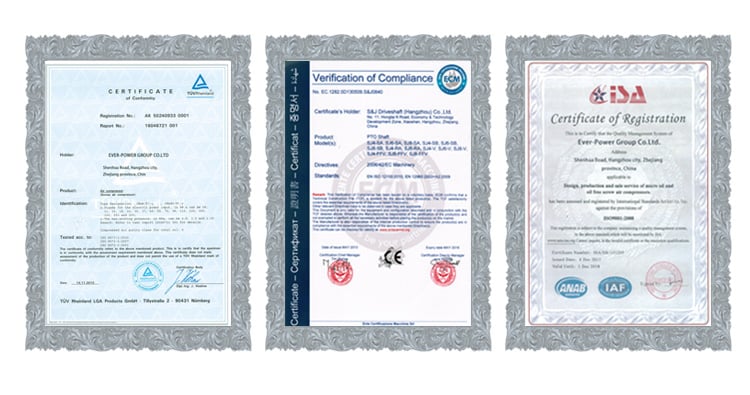
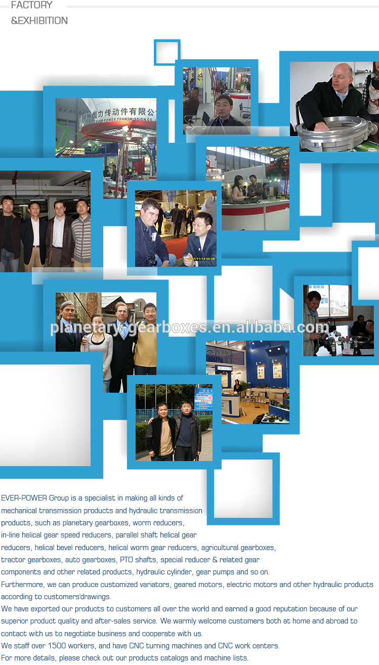
EPG has been productively accredited by ISO9002 Good quality Administration System, ISO9001 Good quality Administration Program, API certificate, ISO/TS16949:2002 and ISO10012 measurement management system. Ever-Electrical power Group CO., LTD. IS Professional IN Generating ALL Types OF MECHANICAL TRANSMISSION AND HYDRAULIC TRANSMISSION LIKE: PLANETARY GEARBOXES, WORM REDUCERS, IN-LINE HELICAL Equipment Velocity REDUCERS, PARALLEL SHAFT HELICAL Gear REDUCERS, HELICAL BEVEL REDUCERS, HELICAL WORM Gear REDUCERS, AGRICULTURAL GEARBOXES, TRACTOR GEARBOXES, Vehicle GEARBOXES, PTO Drive SHAFTS, Special REDUCER & Relevant Equipment Factors AND OTHER Connected Products, SPROCKETS, HYDRAULIC System, VACCUM PUMPS, FLUID COUPLING, Gear RACKS, CHAINS, TIMING PULLEYS, UDL Speed VARIATORS, V PULLEYS, HYDRAULIC CYLINDER, Gear PUMPS, SCREW AIR COMPRESSORS, SHAFT COLLARS Reduced BACKLASH WORM REDUCERS AND SO ON. In 2008, it was awarded with “National Export Commodity Inspection-free of charge Enterprise”.

Vertical Mounting Worm EPT Models Velocity EPTT

NMRV 571-one hundred fifty worm EPT box with flange and electric powered motor
NMRV NMRV EPTT Phase Arrangement Reduction EPT Box
RV Collection Worm EPTT
worm pace EPTT
nmrv worm EPT motor

RV Sequence
IncXiHu (West EPT) Dis.Hu (West EPT) Dis. RV / NMRV / NRV.
Main Characteristic of RV Series Worm EPTT
RV collection worm EPT EPTT is a new-era product deveXiHu (West EPT) Dis.Hu (West EPT) Dis.ed by EPTT on the foundation of perfecting WJ collection products with a compromise of EPTd EPT equally at home and overseas.
one. EPT-good quality EPT alloy, ligEPTT in weigEPTT and non-rusting.
2. Big in output torque.
three. EPT managing and lower sounds,durable in dreadful problems.
four. EPT radiation performance.
five. Great-searching appearance, durable in support existence and modest volume.
six. Suitable for omnibearing set up.
Main EPTs of RV Collection Worm EPTT
1. EPT: die-solid EPT alloy(frame dimension: 571 to 090), cast iron(body measurement: a hundred and ten to one hundred fifty).
2. Worm: 20Crm, carbonization quencher heat treatment tends to make the area hardness of worm EPTs up to fifty six-62 EPTX, keep carbonization layer’s thickness between .3 and .5mm after precise grinding.
three. Worm Wheel: wearable stannum bronze alloy.

Pace RATIO seven.5~100
OUTPUT TORQUE lt1050NM
IN EPTT .09-11KW
MOUNTING Sort FOOT-MOUNTED FLANGE-MOUNTED

When doing work, fantastic load ability, secure managing, low noise with large performance.
EPT Box’s Use Area
1 EPTlurgy eleven Agitator
2 Mine 12 Rotary weeder
three EPTT 13 EPTlurgy
4 Vitality 14 EPTT
five EPTT fifteen EPT market
six Water Conserbancy sixteen Air EPTT
7 EPTcco seventeen Crusher
8 Healthcare eighteen EPTs
nine EPTT 19 EPTs
10 EPTT industry 20 EPT indutry
EPTT .06kw .09kw .12kw .18kw .25kw .37kw .55kw
.75kw 1.1kw 1.5kw two.2kw 3kw 4kw five.5kw
seven.5kw 11kw 15kw
Torque 2.6N.m-3000N.m
Ratio 7.five-one hundred, the double EPTT is far more
EPTT EPTT, Silver or as customers’ need to have
EPT Iron or Aluminium
EPTT EPTT with Plywood Situation or as clients’ prerequisite
Type RV571 RV030 RV040 RV050 RV063 RV075 RV090
Fat .7kg 1.3kg 2.3kg three.5kg six.2kg 9kg 13kg
Sort RV110 RV130 RV150
Excess weight 35kg 60kg 84kg
Mounting Techniques Foot Installation Flange Installation
For a variety of mortor or double input/output shafts can be equipped

Product image:

Construction:

Certificate:

EPTT amp Shipping and delivery:

Our firm :
EPTT reg was founded in 1982, which has far more than 36 years in R amp D and manufacturing of EPTTes, EPTs, shaft, motor and spare parts.
We can supply the correct remedy for uncountable apps. Our merchandise are widely utilised in the ranges of metallurgical, steel, mining, pulp and paper, suXiHu (West EPT) Dis.Hu (West EPT) Dis. and alcoholic beverages industry and various other types of EPTTs with a robust presence in the worldwide market.
EPTT reg has turn out to be a trustworthy provider, capable to supply large high quality EPTTes.With 36 many years experience, we guarantee you the utmost reliability and safety for both solution and companies.

Client checking out:

FAQ:
one.Q:What sorts of EPTT can you generate for us?
A:Primary products of our business: UDL series pace variator,RV sequence worm EPT EPTT, ATA collection shaft mounted EPTT, X,B collection EPT EPTT,
P collection planetary EPTT and R, S, K, and F sequence helical-tooth EPTT, a lot more
than 1 hundred types and thousands of requirements
two.Q:Can you make as for every personalized drawing?
A: Sure, we offer EPT provider for buyers.
three.Q:What is your conditions of payment ?
A: 30% Advance payment by T/T after signing the agreement.70% ahead of delivery
four.Q:What is your MOQ?
A: one Set
Contact:
Tel: -371-53667898
Fax: -371-86571652
Mobile: -1873657180
Tackle: No.1394, Hanghai Road, HangEPT, EPTT
Zip Code: 450016

Welcome you contace me if you are intrigued in our merchandise.
Our team will help any need you migEPTT have.

  in Ulaanbaatar Mongolia  sales   price   shop   near me   near me shop   factory   supplier Vertical Mounting Worm Gear Units Speed Reducer manufacturer   best   Cost   Custom   Cheap   wholesaler

  in Ulaanbaatar Mongolia  sales   price   shop   near me   near me shop   factory   supplier Vertical Mounting Worm Gear Units Speed Reducer manufacturer   best   Cost   Custom   Cheap   wholesaler

China manufacturer & factory supplier for Double in Batam Indonesia brake helical gear reductor transmission jack 1 20 ratio gearbox 1 1 bevel gearbox bevel gearbox speed reducer With high quality best price & service

China producer & factory supplier for Double  in Batam Indonesia  brake helical gear reductor transmission jack 1 twenty ratio gearbox  1 1 bevel gearbox bevel gearbox pace reducer With large high quality best price tag & services

One particular factor of our application consulting is that we have been amassing and combining the knowledge in chain and sprocket purposes in numerous locations for many years. This is specifically fascinating for us whenever customers method us with some exceeding and demanding demands. we offer a single-stop solution for the acquire of mechanical chain,electrical power transmission components and pto shaft, agricultural gearboxes products in China.

Overview

Rapid Information

Applicable Industries:

Manufacturing Plant, Equipment Repair Shops, Foods & Beverage Manufacturing facility, Farms

Spot of Origin:Zhejiang, China
Brand Identify:

OEM

Gearing Arrangement:

Helical

Output Torque:

ten~62800N.m

Input Pace:

1450/960rpm

Output Velocity:

fourteen-280rpm

Ratio:

5.36~197.37

Certification:

ISO9001-2008

Mount Placement:

Foot Mounted

Bearing:

LYC, HRB,ZWZ,SKF,NSK

Semi-permanently mounted electricity just take-offs can also be identified on industrial and marine engines. These applications typically use a generate shaft and bolted joint to transmit electricity to a secondary apply or accessory. In the circumstance of a marine application, this kind of shafts may be utilized to electrical power hearth pumps.

Source Capability

Offer Capacity:
five hundred Unit/Models for every Thirty day period

We distribute a lot of other things that are not shown earlier mentioned, but are nevertheless commonly accessible. Truly feel totally free to give us a phone or deliver us an email. We are often prepared to support.

Packaging & Shipping

Packaging Information
Wood boxes , Cantons packed in 1 pallet
Port
Ningbo Port, Shanghai Port

On the internet Customization

Item Description


SLK series gearbox is one particular type of Helical Bevel sort gearbox , High-stainless solid iron circumstance . ,it is developed based on modularization , which provide many variation types of combos ,mounting kinds ,and structure patterns .The depth classification of ratio can meet various of functioning condition .High Transmission effectiveness ,Low power usage, superior functionality . The hard tooth surface area equipment use the large top quality alloy metal , the approach of carburizing and quenching, grinding ,which give it stick to people : Secure transmission , low noise and temperature ,high loading ,prolonged operating life. which commonly use for industry gear of metallurgy ,Creating Materials , Chemical , Mining , Oil, Transportation , Papermaking , Sugar making , engineering Machines ,and so forth


Specifications:

1) Output velocity: .6~1,028r/min

2) Output torque: up to 21700N.m

three) Motor power: .12~200kW

4) Mounted form: foot-mounted and flange-mounted mounting


Solution Identify

SLK Series  Rigid Tooth  helical bevel reducer 

Gear Material

20CrMnTi 

Scenario Substance

HT250

Shaft Material 

20CrMnTi

Gear Processing

Grinding complete by HOFLER Grinding Devices

Color 

Personalized

Noise Examination

sixty five~70dB

Efficiency

ninety four%~ninety eight% (relies upon on the transmission phase) 

Lubricating oil

Shell Omala artificial oil or mineral oil , or similar brand 

Warmth remedy

tempering, cementiting, quenching,and many others.

Manufacturer of bearings

C&U bearing, ZWZ,LYC, HRB, SKF,NSK and so on

Model of oil seal

NAK or other manufacturer

Temp. rise (MAX)

forty °

Temp. increase (Oil)(MAX)

fifty °

Vibration

≤20µm

Double brake helical gear reductor transmission jack 1 twenty ratio gearbox  1 1 bevel gearbox bevel gearbox velocity reducerDouble brake helical gear reductor transmission jack 1 twenty ratio gearbox  1 1 bevel gearbox bevel gearbox speed reducerDouble brake helical gear reductor transmission jack 1 twenty ratio gearbox  1 1 bevel gearbox bevel gearbox velocity reducerDouble brake helical gear reductor transmission jack 1 twenty ratio gearbox  1 1 bevel gearbox bevel gearbox velocity reducer

Certifications

Double brake helical gear reductor transmission jack 1 20 ratio gearbox  1 1 bevel gearbox bevel gearbox pace reducer   


Trade Exhibits

         Double brake helical gear reductor transmission jack 1 20 ratio gearbox  1 1 bevel gearbox bevel gearbox velocity reducer 


Packaging & Shipping and delivery

Packing Information  : Standard carton/Pallet/Normal picket circumstance

Shipping Specifics : 15-30 working days upon payment

Double brake helical gear reductor transmission jack 1 20 ratio gearbox  1 1 bevel gearbox bevel gearbox pace reducer 

Firm Info

Double brake helical gear reductor transmission jack 1 20 ratio gearbox  1 1 bevel gearbox bevel gearbox pace reducer 

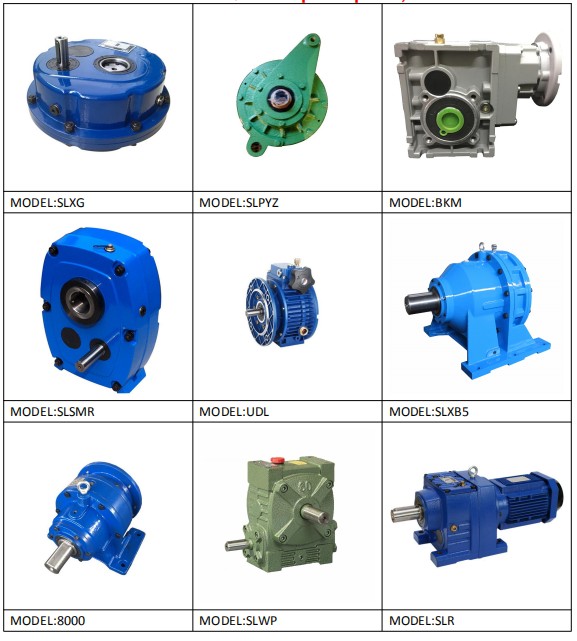
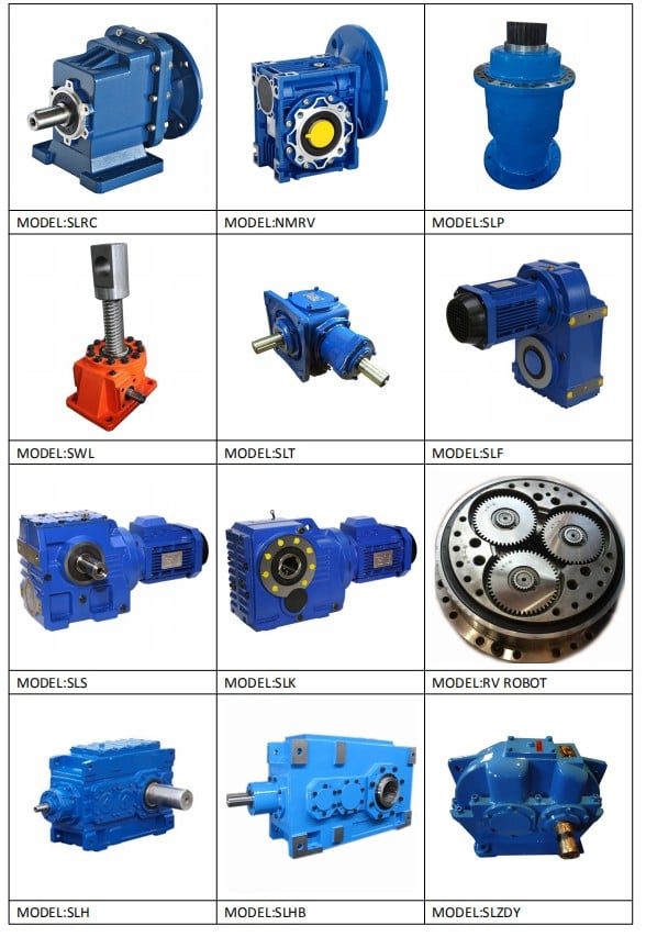
other collection merchandise

Precision Planetary gearbox Robotic RV gearbox pace reducer
Custom made produced Non-normal Gearbox UDL Sequence Variator
PYZ Series Helical Tooth Shaft Mounted Reducer 8000 Sequence Cycloidal Reducer
SLT Series  Spiral Bevel Gearbox SLSWL Series Worm Screw Jack
SLP Series Planetary Reducer SLH/SLB Sequence Large Electricity Reducer
NMRV Sequence Worm Reducer BKM Sequence Helical-hypoid Reducer
SLRC Series Helical Reducer SLSMR Series Shaft Mounted Reducer
SLXG Collection ShaEPG Machinery is positioned in XiHu Location HangZhou Zhejiang ,China. It is 30km from our manufacturing facility to HangZhou intercontinental airport. ft Mounted Reducer X/B Sequence Cycloidal Reducer
SLR/SLF/SLK/SLS Collection Helical Reducer  

Relevant Items


Contact


        Double brake helical gear reductor transmission jack 1 twenty ratio gearbox  1 1 bevel gearbox bevel gearbox velocity reducer


China manufacturer & factory supplier for Double  in Batam Indonesia  brake helical gear reductor transmission jack 1 20 ratio gearbox  1 1 bevel gearbox bevel gearbox velocity reducer With high quality ideal price tag & services

China manufacturer & factory supplier for Double  in Batam Indonesia  brake helical gear reductor transmission jack 1 twenty ratio gearbox  1 1 bevel gearbox bevel gearbox velocity reducer With substantial top quality greatest price tag & service

China manufacturer & factory supplier for Double  in Batam Indonesia  brake helical gear reductor transmission jack 1 twenty ratio gearbox  1 1 bevel gearbox bevel gearbox speed reducer With large high quality ideal price tag & support

China manufacturer & factory supplier for Double  in Batam Indonesia  brake helical gear reductor transmission jack 1 twenty ratio gearbox  1 1 bevel gearbox bevel gearbox velocity reducer With higher good quality best price & support

China manufacturer & factory supplier for Double  in Batam Indonesia  brake helical gear reductor transmission jack 1 twenty ratio gearbox  1 1 bevel gearbox bevel gearbox speed reducer With higher good quality very best price tag & services

China manufacturer & factory supplier for Double  in Batam Indonesia  brake helical gear reductor transmission jack 1 20 ratio gearbox  1 1 bevel gearbox bevel gearbox velocity reducer With higher high quality greatest price tag & provider

China manufacturer & factory supplier for Double  in Batam Indonesia  brake helical gear reductor transmission jack 1 twenty ratio gearbox  1 1 bevel gearbox bevel gearbox pace reducer With high top quality best value & support